
0
Owner's of the Pioneer DJ Equipment DJM-900NXS gave it a score of 0 out of 5. Here's how the scores stacked up:
En
7
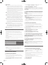
Connections
Connections
Be sure to turn off the power and unplug the power cord from the power outlet whenever making or changing connections.
Refer to the operating instructions for the component to be connected.
Connect the power cord after all the connections between devices have been completed.
Be sure to use the included power cord.
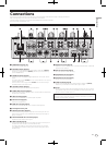
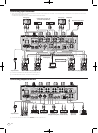
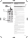
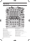
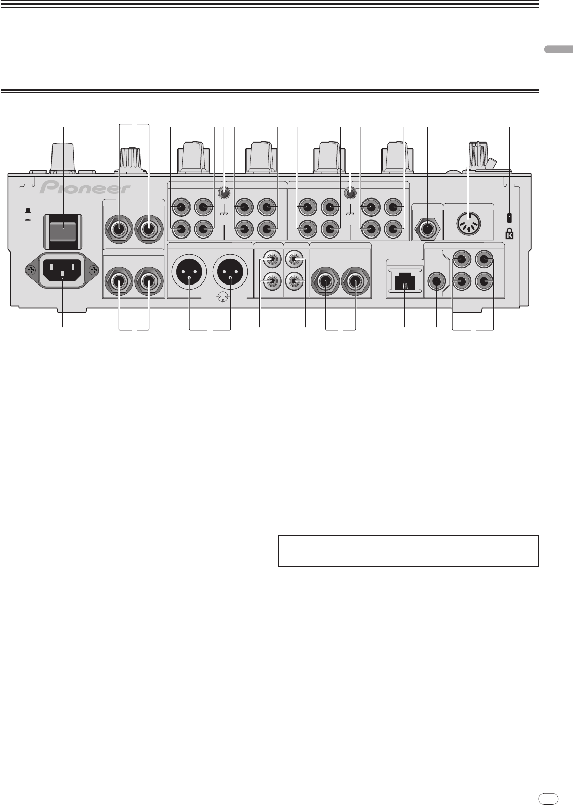
Rear panel
OFF
RETURN
L
L
L
1 GND
2 HOT
3 COLD
L
R
L
L
IN
CH3
CH4
CH1CH2
R
R
R
R
L
R
R
PHONO
CH 4CH 3
CD/LINE
L
R
PHONO
CH 1
CD/LINE
SIGNAL GNDSIGNAL GND
TRS
CD/LINELINE
MASTER1 MASTER2
REC OUT
BOOTH
MIC2
MIDI OUT
DIGITAL
MASTER
OUT
LINK
L
R
CH 2
CD/LINELINE
(MONO)
LR
(MONO)
SEND
POWER
AC IN
ON
1 34 3446 465 5 7 8 92
ef bci adh g
1 POWER button (page 14)
Turns this unit’s power on and off.
2 RETURN terminals (page 8)
Connect to the output terminal of an external effector. When the [L (MONO)]
channel only is connected, the [L (MONO)] channel input is simultaneously
input to the [R] channel.
3 PHONO terminals (page 8)
Connect to a phono level (MM cartridge) output device. Do not input line level
signals.
To connect a device to the [PHONO] terminals, remove the short-circuit pin plug
inserted in the terminals.
Insert this short-circuit pin plug into the [PHONO] terminals when nothing is
connected to them to cut external noise.
4 CD/
LINE terminals (page 8)
Connect to a DJ player or a line level output component.
5 SIGNAL GND terminal (page 8)
Connect an analog player’s ground wire here. This helps reduce noise when the
analog player is connected.
6 LINE terminals (page 8)
Connect to a cassette deck or a line level output component.
7 MIC2 terminal (page 8)
Connect a microphone here.
8 MIDI OUT terminal (page 8)
Connect this to the MIDI IN terminal on an external MIDI sequencer.
9 Kensington security slot
a DIGITAL IN terminal (page 8)
Connect these to the digital coaxial output terminals on DJ players, etc. The
sound may be momentarily interrupted when the output signal sampling fre-
quency is switched.
b DIGITAL MASTER OUT terminals (page 8)
Outputs the master channel audio signals.
c LINK terminal (page 8)
Connect these to the LINK terminals on Pioneer DJ players or the LAN ports of
computers on which rekordbox is installed (PRO DJ LINK).
To connect multiple devices, use a switching hub (commercially available).
Use a 100Base-TX-compatible switching hub. Some switching hubs may not
operate properly.
d BOOTH terminals (page 8)
Output terminals for a booth monitor, compatible with balanced or unbalanced
output for a TRS connector.
e REC OUT terminals (page 8)
This is an output terminal for recording.
f MASTER2 terminals (page 8)
Connect to a power amplifier, etc.
g MASTER1 terminals (page 8)
Connect to a power amplifier, etc.
h SEND terminals (page 8)
Connect to the input terminal of an external effector. When the [L (MONO)]
channel only is connected, a monaural audio signal is output.
i AC IN
Connect to a power outlet using the included power cord. Wait until all connec-
tions between the equipment are completed before connecting the power cord.
Be sure to use the included power cord.
WARNING
The short-circuit pin plugs out of the reach of children and infants. If accidentally
swallowed, contact a doctor immediately.


Find Your Products By Category
Please Login
