
0
Owner's of the Pioneer DJ Equipment Pioneer DJ Equipment gave it a score of 0 out of 5. Here's how the scores stacked up:

10
En
Connections and part names
! Wait until all connections between devices have been completed
before connecting the AC adapter.
Be sure to turn off the power and unplug the AC adapter from the
power outlet before making or changing connections between
devices.
Refer to the operating instructions for the component to be
connected.
! Only use the AC adapter included with this unit.
! Power to this unit is supplied by the AC adapter or by USB bus
power.
This unit can be used by connecting it to a computer using a USB
cable, even without connecting the AC adapter.
! Connect this unit and the computer directly using the included USB
cable.
! A USB hub cannot be used.
Notes on running this unit with USB bus power
! When using this unit on USB bus power, supply power to the con-
nected computer from the AC power supply. Do not run the com-
puter on its battery.
! In cases like the ones below, the power may be insufficient and this
unit may not operate on USB bus power.
— When the computer’s USB power supply capacity is insufficient.
— When other USB devices are connected to the computer.
If this unit does not operate on USB bus power, connect the included
AC adapter.
! The following limitations apply when operating on USB bus power:
— The jog dial indicator will not light.
— The [MASTER OUT 1] (XLR output) channel is not output.
— The [MIC1], [MIC2] and [AUX IN] terminals cannot be used.
— The indicators are dimmer than when using the AC adapter.
To use the unit without these limitations, connect the included AC
adapter.
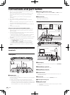
Connecting the input/output
terminals
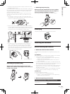
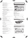
Front panel
PHONES
MIC 2
MIC/AUX THRU
ONOFF
PHONES
MIC 2
MIC/AUX THRU
ONOFF
123
1 PHONES jacks
Connect headphones here.
Both stereo phone plugs (Ø 6.3 mm) and stereo mini phone plugs (Ø
3.5 mm) can be used.
For details, see Monitoring sound with headphones on page 27.
! There are two input jacks, both a stereo phones jack and a mini
phones jack, but do not use both simultaneously. If both are used
simultaneously, when one is disconnected and/or connected, the
volume of the other may increase or decrease suddenly.
2 MIC/AUX THRU selector switch
Set this to [ON] if you want to output the [MIC2] and [AUX] channels
directly.
= Outputting the microphone and AUX sound directly (p.29)
3 MIC2 terminal
Connect a microphone here.
= Using a microphone (p.28)
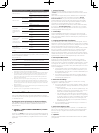
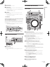
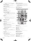
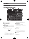
Rear panel
VOLAUX INMASTER OUT 2MASTER OUT 1MASTER ATT.
MAX
LRLL
1GND
2 HOT
3 COLD
RR
-12 dB -6 dB0 dB
MIN
ONUSBOFF DC IN
5 V
VOLAUX INMASTER OUT 2MASTER OUT 1MASTER ATT.
MAX
LRLL
1GND
2 HOT
3 COLD
RR
-12 dB-6 dB0 dB
MIN
R
L
R
L
51
2
3 4
ONUSB OFF DC IN
5 V
8 9 a6 7
To audio input
terminals
To audio output
terminals
Portable
audio
device
Component,
amplifier,
powered speaker, etc.
Computer
AC adapter
(included)
To power outlet
1 MASTER ATT.
Sets the attenuation level of the sound output from the [MASTER1]
terminal.
2 MASTER OUT 1 terminals
Connect powered speakers, etc., here.
3 MASTER OUT 2 terminals
Connect to a power amplifier, etc.
4 AUX IN terminal
Connect to the output terminal of an external device (sampler, por-
table audio device, etc.)
5 VOL control
Adjusts the audio level input to the [AUX IN] terminals.
6 Kensington security slot
7
USB terminal
Connect to a computer.
! Connect this unit and the computer directly using the included
USB cable.
! A USB hub cannot be used.


Find Your Products By Category
Please Login
